A Logic Gate is basically an electronic circuit that deals with binary numbers i.e. either 0 (low) or 1(high). It is a basic building block of digital circuits. It has one or more inputs and one output. The relationship between inputs and output is based on certain logic and hence termed as Logic Gate.
There are three basic logic gates – AND, OR and NOT gate.
Universal Gates – Gates from which any digital circuit and other logic gates can be implemented are called Universal Logic Gates. There are two universal gates- NAND and NOR.
There are two derived gates – EX-OR and EX-NOR.
NOT Gate – It has one input and one output. It reverses the input state.The output is 1(high) when input is 0 (low) and vice versa.
Logic Symbol –
Truth Table –

AND Gate – It has two inputs and one output. The output is high only when all the inputs are high otherwise the output is low. A dot (.) is used to show the AND operation.
Y = A . B
Logic Symbol –

Truth Table –

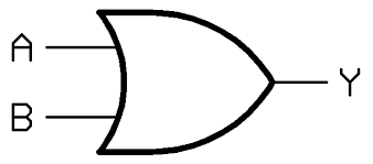
OR Gate – It has two inputs and one output. The output is high when any one or more of the inputs are high. A dot (+) is used to show the OR operation.
Y = A + B
Logic Symbol –
Truth Table –

